
Technical Guide
EDM For Electronics Connectors
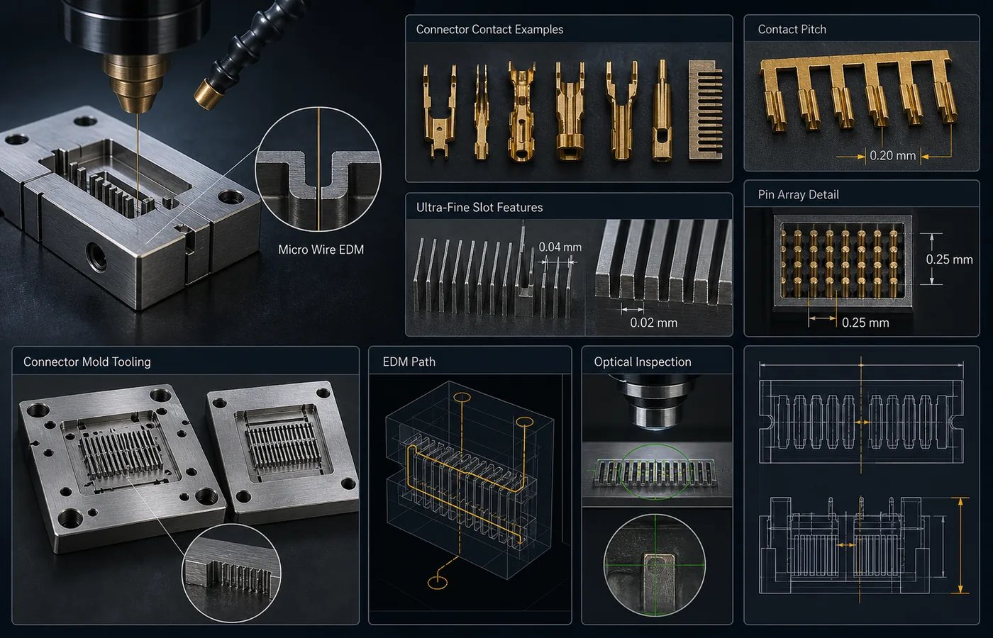
Review EDM For Electronics Connectors in relation to material behavior, tolerance, surface finish and inspection planning before sending drawings.
EDM Feasibility Notes
We review EDM feasibility for the selected material using the drawing geometry, conductive material condition, tolerance, surface finish, quantity and inspection requirements.
Technical Explanation
This guide helps prepare EDM drawings by reviewing material conductivity, process access, tolerance, surface finish and inspection requirements.
Project question: How is EDM used for electronics connector tooling?
Recast Layer / Surface Integrity Notes
Surface integrity, recast layer, micro-crack risk, post-processing and inspection depend on the material, EDM process, geometry and machine setup.
Technical Review Checklist
| Concept | EDM for Electronics Connectors |
|---|---|
| How we use this guide | We use these points to discuss EDM process fit before confirming the production approach. |
| Drawing review | We confirm material conductivity, feature access, geometry, thickness, tolerance, surface finish and inspection method from your drawing. |
| Project details | Please include drawings, material grade, critical dimensions and any required inspection or surface-integrity controls. |
Inspection and Capability Reference
Inspection planning may include dimensional measurement, optical measurement, surface roughness checks and report requirements according to the drawing.
Technical Note
Use this technical guide to prepare your drawing and key requirements, then contact our team when you need project-specific EDM review.
Need help reviewing an EDM drawing?
Send a drawing question, material details and key requirements for technical review.
- Drawing or part sketch
- Material grade
- Thickness / part size
- Quantity
STEP/STP, DXF, DWG, PDF, IGS/IGES or ZIP.
Confidential drawing review. NDA support available on request.
Frequently Asked Questions
What should be reviewed for EDM for Electronics Connectors?
Material conductivity, thickness, feature access, geometry, tolerance, surface finish and inspection method should be reviewed from the drawing.
How does EDM for Electronics Connectors affect process planning?
The machining route depends on the drawing, material condition, geometry, quality requirements and available inspection method.
Which drawing details are important for this topic?
Include material grade, critical dimensions, datums, tolerance, surface finish and inspection requirements.
When should surface integrity be reviewed?
Surface integrity should be reviewed when recast layer, micro-crack risk, fatigue performance, sealing surfaces or post-processing are important.
What should be sent for technical review?
Send drawings, material grade, target tolerance, surface requirements, critical dimensions and any inspection or report expectations.